Proposal for Sarah & Max Mangum
1019 Pine
Street
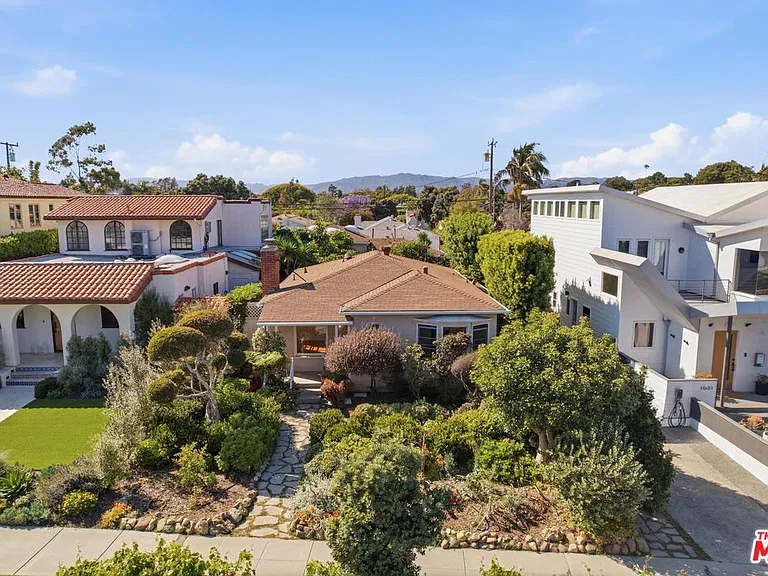
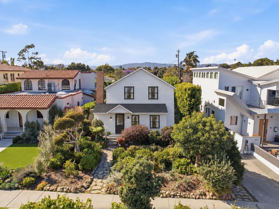
PINE addition + rear unit demo. First-floor remodel, a new second story, and removal of the rear guest house — Santa Monica, California 90405.
I — The Project
A remodel, a new story, a cleared yard.
“Remodel 935 sq ft, demolish 37 sq ft and 304 sq ft new on first floor of existing SFD. New 793 sq ft second floor addition. Residence to be 4 bedroom + 3.5 Bath.” — A0.1
2,032 SF
Total residence
793 SF
Second-floor addition
935 SF
Existing area to be remodeled
4 bed · 3.5 bath
Proposed program
360 SF
Existing 1-car garage to remain
481 SF
Rear guest house to be demolished
+ Full project data, zoning & team− Hide project data
- Existing house area
- 993 SF
- Existing area to be remodeled
- 935 SF
- Existing area to be demolished
- 37 SF
- New first-floor area
- 304 SF
- Second-floor addition
- 793 SF
- Total residence
- 2,032 SF
- Existing 1-car garage to remain
- 360 SF
- Rear guest house to be demolished
- 481 SF
- Proposed program
- 4 bed · 3.5 bath
- Lot area
- 5,330 SF
- Floor area incl. garage, vs 2,398.5 SF max FAR
- 2,392 SF
- Existing to proposed building height
- 14′-0″ → 28′-0″
- Zoning
- R1
- Occupancy
- R-3
- Construction type
- V-b
- Existing stories
- 1
- Sprinklers
- To be installed
- APN
- 4284011007
- Guest house demo permit
- 26BLD-3436
- First / second floor elevation
- 93.75′ / 105.75′
- Owner
- Sarah + Max Mangum
- Architect
- OPEN MODE — Sarah Le Clerc, AIA NCARB
- Interior designer
- Anastasia Ratia
- Structural (as listed on A0.1)
- JGL Engineering — Joe Garcia
- Energy analysis
- NRG Compliance, LLC — Mario Bertacco
- Surveyor
- Taro Okada
- Contractor
- California Green Dreams Remodeling
The bid set cover (A0.1) lists 935 SF remodeled + 304 SF new first floor + 793 SF second floor = 2,032 SF. The trade scope, written from the earlier 9.18.26 architectural set, cites 1,242 SF first floor + 795 SF second floor = 2,037 SF and notes these are design areas, not takeoff quantities. Approximately 2,030 SF, pending plan reconciliation.
II — The Drawings
Plan set, as drawn
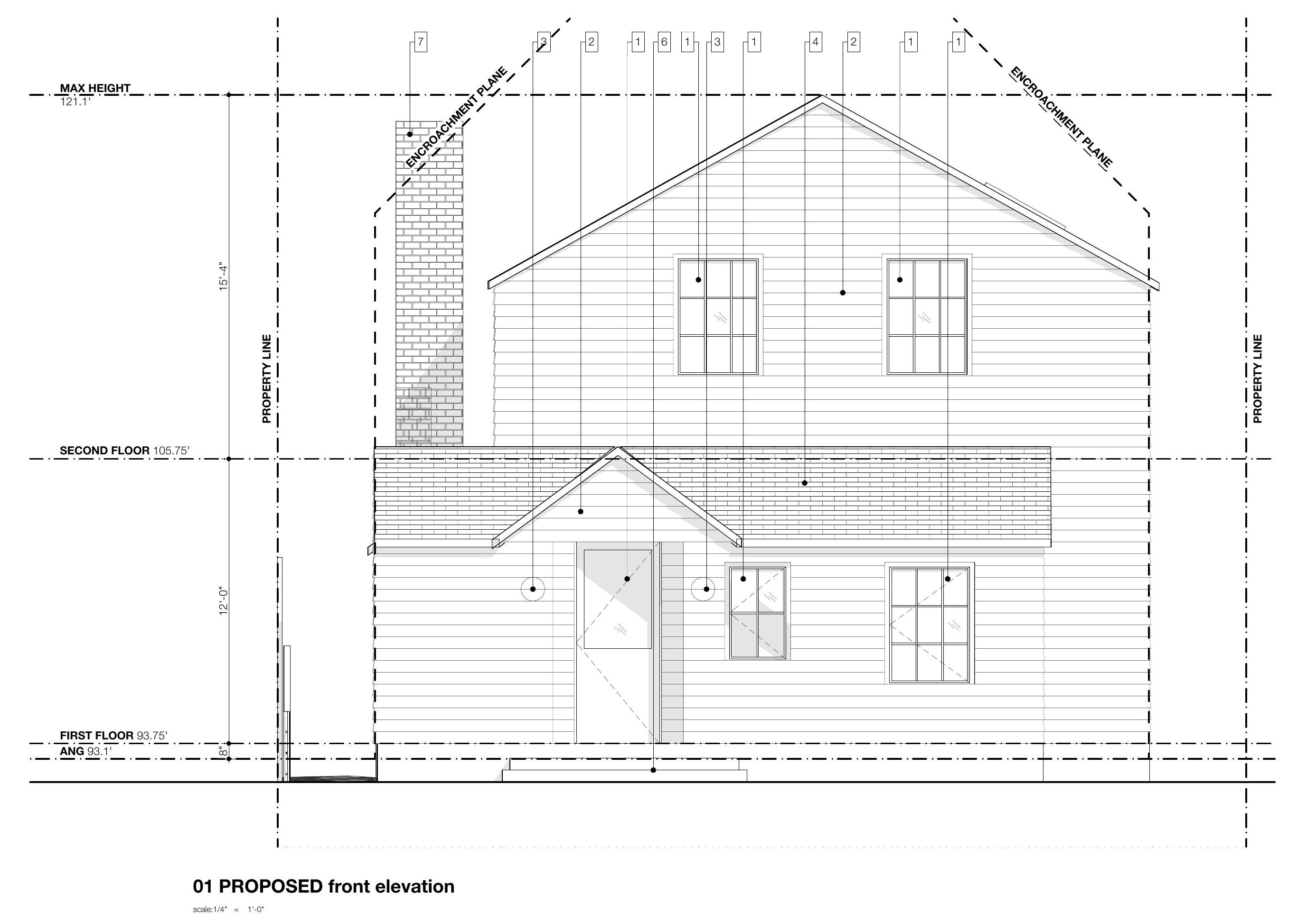
The trade scope was prepared from OPEN MODE's 9.18.26 city submittal set (21 sheets, A0.1–A7.0) and Thang Le & Associates structural drawings dated September 25, 2026 (S1.1–S7.0, SSW1–SSW2). The drawings shown here are the later 10.12.26 bid set. Architectural sheets are marked NOT FOR CONSTRUCTION.
Mock-up check
Drawing vs. rendering
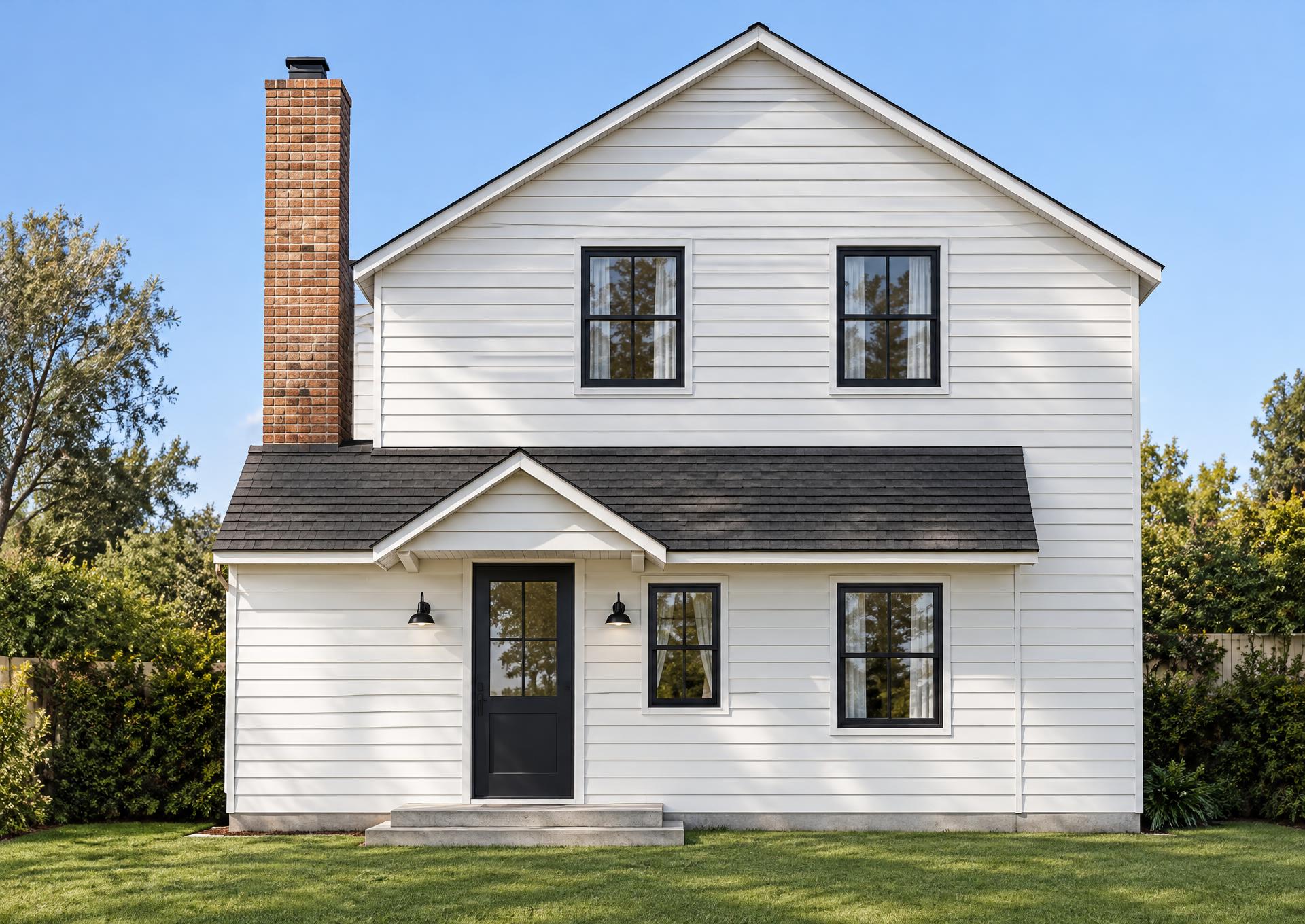
Each A2.2 elevation next to an AI mock-up made from it. Mock-ups are rough visual checks only; colors and materials are placeholders, and the drawings govern.
III — Scope of Work
The work, trade by trade
Wording taken directly from the trade scope. No pricing or durations are given in it.
01Preconstruction and project coordination
Site & Structure+
Entire property, main house, rear guest house, retained garage, and approved utility routes.
- 1Reconcile the architectural and structural sets with the architect, structural engineer, energy consultant and City; obtain the approved construction set and applicable building, demolition and trade permits before starting.
- 2Confirm survey boundaries, setbacks, first-floor elevation 93.75 feet, second-floor elevation 105.75 feet, proposed height controls, and the work limits. Use the licensed survey rather than conflicting property-line annotations.
- 3Obtain the geotechnical report referenced on S1.1, LK Geotechnical Engineering report 26-0804 dated September 23, 2026, and its approved addenda. Confirm excavation, bearing, compaction and observation requirements.
- 4Conduct a documented existing-condition walkthrough. Locate utilities, identify retained framing and fireplace, inspect garage separation from the guest house, and record surrounding improvements to be protected.
- 5Collect client product information for doors/windows, appliances, plumbing valves, lighting, equipment, flooring, tile and millwork before setting openings and rough connections. Prepare trade coordination/shop drawings where required.
- 6Establish safe site access, barriers, sanitary facilities, protected material storage, dust control, temporary weather protection and temporary utilities. Protect survey monuments, trees, adjacent property and retained construction.
- 7Implement erosion/sediment controls, covered stockpiles, concrete washout containment and waste segregation required by A0.3 and the approved City runoff conditions. Obtain Public Works permission before right-of-way staging or excavation.
- 8Schedule geotechnical observations, structural observations and required independent special inspections with the responsible consultants. S1.1 assigns employment of special inspectors to the owner; CGD coordinates access and sequences its labor around those inspections.
02Demolition and selective removals
Site & Structure+
Existing first-floor interior and roof; 481-square-foot rear guest house; connections to retained garage.
- 1Mark the A1.3 removal boundaries against retained construction. Protect the existing fireplace, garage, adjoining improvements and any first-floor framing retained on S2.1.
- 2Complete required pre-demolition hazardous-material surveys and agency notifications. A0.1 calls for SCAQMD demolition notification before demolition permit issuance; confirm current filing timing with the responsible agency. If regulated materials are found, complete approved abatement/clearance before ordinary demolition.
- 3Isolate electrical, gas, water and sewer services feeding removed work. Licensed trades disconnect and safely cap abandoned lines; maintain required services to retained structures.
- 4Install engineered temporary support where bearing walls, roof members or shared garage/guest-house construction will be removed. Do not use the architectural nonbearing demolition linework to decide structural removal independently.
- 5Remove first-floor partitions, doors/windows, cabinetry, fixtures, finishes and portions of exterior walls indicated for removal on A1.3 to accommodate the proposed A2.0 layout. Retain only the components specifically identified to remain.
- 6Remove the main-house roof construction within the indicated demolition limits for the second-story addition and new roof. Maintain staged weather protection.
- 7Demolish the rear guest-house roof, walls, interior, fixtures and associated construction within the designated footprint; separate it carefully from the retained garage. Confirm foundation/slab removal depth and utility abandonment limits because these are not fully detailed.
- 8Remove guest-house portions of the shared rear roof and temporarily dry-in the garage. Prepare the remaining garage enclosure and roof for the approved reconstruction.
- 9Haul debris to approved facilities, segregate recyclable construction waste, maintain disposal records, and leave exposed substrates safe and ready for foundation and framing work.
03Foundation and structural concrete
Site & Structure+
Main-house new continuous footings, pads, designated existing-footing connections, Strong-Wall supports, crawlspace access and entry steps. Garage concrete only where confirmed by approved garage design.
- 1Lay out every new footing, pad, holdown and Strong-Wall anchor position from S2.1 and its keyed details; distinguish new from existing foundations. Confirm excavation limits and underground service conflicts before digging.
- 2Shore retained work and excavate new perimeter/interior foundation areas in a sequence approved for existing construction. Do not undermine adjacent or retained footings. Have the geotechnical representative observe bearing soil and prescribe preparation.
- 3Prepare bearing surfaces, approved fill and compaction. S1.1 identifies a 24-inch minimum footing embedment and 1,500 psf assumed allowable bearing; follow actual keyed details and the approved geotechnical report where more restrictive.
- 4Construct continuous stemwall/footing forms to S3.0: typical footing width is 1 foot 4 inches and minimum depth is 24 inches where indicated. Install the specified continuous bars, corner bars, vertical reinforcement at taller stems, and exact section geometry without generalizing these dimensions to every footing.
- 5Form individual post pads per S2.1/S3.1. Typical pads shown in S3.1 are 3 feet square with five No. 4 bars each way at the bottom; use each location-specific callout. Construct new-to-existing pad and footing transitions with the specified dowels and adhesive systems.
- 6At the rear Strong-Wall line, provide the specially called-out 3-foot by 8-foot by 36-inch-thick footing with eight No. 5 bars each way at the bottom, as shown on S2.1. Set proprietary SSWAB anchors using templates and coordinate embedment, edge distance, reinforcement and concrete strength with SSW1 and the engineer.
- 7Drill and clean existing concrete for the specified epoxy dowels and holdown anchors. Follow the listed adhesive installation conditions and special-inspection requirements; do not replace SET-3G/SET-XP or change embedment without approval.
- 8Install anchor bolts, plate washers, holdown rods, sleeves and required crawlspace access concrete per S3.1. Coordinate below-floor plumbing and electrical sleeves; follow S1.2 pipe-at-footing detail without cutting reinforcement.
- 9Complete form, reinforcing, anchor, underground-utility and geotechnical inspections before pouring. General structural notes identify 2,500 psi concrete for foundations/slabs unless otherwise noted; use higher strength wherever a keyed design or approved anchor requirement calls for it.
- 10Place, consolidate and cure concrete; maintain anchor alignment and protect reinforcement cover. Construct indicated front entry steps to coordinated A5.1/01 and S1.2/06 dimensions, with consistent risers, tread geometry and landings.
- 11After strength/release, strip forms, inspect finish and anchors, waterproof applicable buried surfaces, and backfill/compact without damaging foundations or membranes. Provide required material/inspection records.
04Framing and structural carpentry
Site & Structure+
First-floor retained/new framing, first-floor walls, second-floor structure, roof, skylights, stairs, chases and garage demolition interface.
- 1Confirm load paths and bearing locations against installed foundations before erecting framing. Inspect retained floor framing and report damage; S2.1 identifies portions to remain and new 2x6 floor joists at 16 inches on center where shown.
- 2Install treated sill plates, anchorage, posts, girders, floor joists, blocking and rim members at the exact S2.1 locations. Complete retained-to-new floor connections using S3.0/S3.1 details and specified hangers/ledgers.
- 3Frame first-floor exterior and interior walls, bearing lines, door/window openings, pantry, laundry, powder room, Bath 1, Bedroom 1/closet, kitchen/living/dining areas, stair opening and mechanical chase to A2.0 and structural requirements. Architectural interior studs are 2x4 unless otherwise noted; engineered wall requirements govern.
- 4Install the second-floor system on S2.2, including designated 2x12 joists at 16 inches on center, 7 x 11-1/4-inch and 5-1/4 x 11-1/4-inch PSL members where called out, timber beams/posts, joist hangers and beam-to-post connections. Do not extend one beam size to other locations.
- 5Provide floor sheathing with the specified grade/thickness, joints, blocking, adhesive and nailing. Coordinate the floor-plan callout with structural sheathing notes before purchase where labels conflict.
- 6Frame the second-floor bedrooms, closets, primary suite, bathrooms, hallway and stair landing. Frame niches, tub/shower recesses and equipment access only after approved finish/fixture layouts.
- 7Install each plywood shear-wall line, holdown and strap per S2.1-S2.3 and S7.0. Match wall mark, length, panel grade, edge/field fastening, boundary studs, blocking and sill transfer. Coordinate the differing shear schedules on the plan sheets and S7.0 through the engineer.
- 8Install the designated Simpson Steel Strong-Wall assemblies, including SSW18x8 and SSW24x8 where tagged, with the scheduled proprietary fasteners, anchorage, transfer kits and top connections. Use SSW1/SSW2 and current approved product documentation; do not field cut or substitute panels.
- 9Frame roof rafters, ridge members, ceiling joists, hips/valleys, eaves, outriggers and lower roof areas per S2.3/S5.0/S6.0. The plan shows 2x10 rafters and 2x6 ceiling joists at 16 inches on center in designated areas; complete all location-specific members and slope changes.
- 10Frame skylight openings with doubled members, headouts and hangers per S6.0/07; confirm three roof-plan units and the separate kitchen skylight reference before cutting. Install roof sheathing and roof/wall diaphragm connections.
- 11Provide blocking for cabinets, vanities, counters, handrails/guards, glass hinges, towel accessories, fans, heavy fixtures and equipment. Provide fireblocking, draftstopping and approved penetrations; keep required access openings clear.
- 12Reconstruct the garage demolition interface, wall closure and hip-roof portions only to the coordinated garage framing design. The architectural index lists a garage structural sheet but the supplied structural PDF has no separate keyed garage plan; obtain that detail before reconstruction.
- 13Complete structural observations, shear/diaphragm/holdown and rough framing inspections while fasteners remain visible. Correct documented deficiencies before insulation and drywall.
05Electrical
Building Systems+
All remodeled first-floor rooms, all second-floor rooms and circulation, exterior fixtures, equipment connections, retained garage and approved underground service route.
- 1Prepare a coordinated circuit, receptacle, lighting and service layout from the architectural/RCP information and applicable electrical code. The supplied set has no complete E-sheet circuit plan, panel schedule, load calculation or service rating; verify these before roughing.
- 2Calculate dwelling/appliance/HVAC loads, inspect the existing service, and determine required panel/service work through the designer and utility. Do not assume a 200-amp replacement or a particular EV/solar/battery system from general mandatory notes.
- 3Coordinate overhead utility undergrounding expressly required by A0.1/A0.3. Install the approved onsite conduits, sweeps, trench bedding and service raceways; obtain utility design and Public Works excavation/traffic approvals before offsite work. Final routing and utility-owned equipment remain subject to utility approval.
- 4Rough wiring, boxes and grounding/bonding for the entry, laundry, powder room, Bath 1, Bedroom 1/closet, pantry, kitchen/island, dining and living rooms; second-floor bedrooms/closets, primary bathroom, Bath 2, hall and stairs. Protect cables at framing penetrations and maintain working clearances.
- 5Provide required small-appliance circuits for the kitchen/dining/pantry, laundry circuit, bathroom receptacle circuits and dedicated appliance circuits as applicable. Coordinate two dishwashers, refrigerator, 48-inch range/hood, washer/dryer and equipment ratings with client cut sheets.
- 6Provide receptacles at required wall and counter locations and approved island provisions; GFCI, AFCI, tamper-resistant and weather-resistant protection as required by the governing edition. Final count and mounting positions shall be confirmed in the electrical layout.
- 7Rough lighting/control wiring from A7.0, including kitchen island lights, room/closet lighting, bath vanity/wet-area lighting, stair lighting controlled at appropriate levels, and A2.2 exterior fixtures. Confirm unfinished fixture types and missing switch details before closing walls.
- 8Provide hardwired interconnected smoke/CO alarms with battery backup at bedrooms, outside sleeping areas and each required level per A2.0 and adopted code. Coordinate fan-rated boxes and dedicated connections/disconnects for HVAC, hood, exhaust fans and other selected equipment.
- 9Provide approved firestopping and seal envelope penetrations; coordinate with shear-wall designer before placing panels or large recesses in structural walls. Complete rough electrical inspection before covering.
- 10After finishes, install client-supplied luminaires, fans, devices and plates; include required high-efficacy lighting and current Energy Code controls. Do not rely on the older 40-lumens-per-watt RCP note as the sole compliance criterion.
- 11Label circuits, test polarity/grounding, GFCI/AFCI function, alarms and switching, verify equipment operation, and complete electrical final and utility energization release. Provide circuit directory and available installed-product information.
06Mechanical HVAC and ventilation
Building Systems+
Conditioned rooms on both floors; mechanical chases and underfloor distribution; all bath/powder exhausts; kitchen hood; laundry exhaust.
- 1Use the energy report and heating/cooling load summary to prepare equipment and duct submittals. The report models one central gas furnace and split air conditioner with underfloor supply and return distribution; reconcile this with the section mechanical space and verify equipment locations, capacity, access and utility restrictions before purchase.
- 2Inspect retained mechanical components, disconnect work within demolition limits, and determine the reuse/removal scope through approved design. Protect open ducts from construction dust.
- 3Install equipment supports, isolation pads/hangers, service access and rough routes through the designated chases without cutting engineered framing. Coordinate condenser placement, noise control and clearances with approved site/elevation requirements.
- 4Install new supply and return ducts/plenums serving the kitchen, living/dining areas, bedrooms and other conditioned rooms per the mechanical layout. General notes specify galvanized sheet metal; flex duct requires written designer/owner approval. Provide listed sealing, supports, vibration isolation and acoustic treatment.
- 5Insulate ducts to the approved energy report rather than older R-4.2 boilerplate. A0.6 models R-6 duct insulation; verify the final registered compliance document and any higher required value for actual routing.
- 6Install condensate drain, refrigerant lines and insulation, auxiliary overflow protection where required, combustion air/flue for gas equipment if approved, and required controls/electrical interlock connections. Seal and flash exterior/roof penetrations.
- 7Install bathroom/powder-room exhaust fans at the locations indicated on A2.0/A7.0, ducted directly outdoors with backdraft dampers. Use Energy Star units and accessible humidistat controls unless the approved whole-house ventilation design permits another control.
- 8Provide whole-dwelling ventilation per the approved Energy Code compliance design. A0.6 models a 95-cfm exhaust ventilation system; coordinate fan duty, controls and verification without assuming every local exhaust fan satisfies this requirement.
- 9Install the 48-inch range hood connection and exterior duct, sized to the actual client hood and appliance. A2.0 notes a minimum 100-cfm kitchen exhaust; verify actual hood capture, airflow and any required makeup air, especially for a high-output range.
- 10Install laundry dryer exhaust with smooth approved duct, accessible transition and exterior termination. The plans note a 4-inch minimum, 14-foot route with two elbows, maximum 6-foot unconcealed flex connector and closet makeup-air opening; resolve these older notes with adopted code and the dryer listing before rough work.
- 11Complete rough mechanical inspection and required duct/ventilation field verification. Protect open grilles and equipment during painting and sanding.
- 12Install client equipment, finish grilles and thermostat; start up, balance supply/return air, verify exhaust airflow and condensate disposal, and submit required compliance/field-testing records. Instruct the client on operation and maintenance.
07Plumbing and gas piping
Building Systems+
Powder room and Bath 1 on first floor; Bath 2 and primary bath on second floor; kitchen, laundry, water-heating connections, chases, underfloor and approved utility routes.
- 1Confirm fixture counts, drain locations, valve bodies, tub dimensions, appliance connections and water-heater disposition using client product data and the architect layout. No engineered P-sheet routing or sizing schedule is supplied; complete approved sizing and layout before rough work.
- 2Isolate/remove plumbing in demolition areas and cap guest-house domestic, drain/vent and gas branches at approved locations. Inspect existing house service and sewer tie-in condition; do not assume a complete offsite sewer replacement from the recommendation in A0.3.
- 3Install approved underground/underfloor drainage, vent, cleanout and water-service connections for the proposed residence. Coordinate sleeves and setbacks from foundations per S1.2/04; maintain required drain slopes, supports and accessible cleanouts.
- 4Provide new rigid copper water lines per A0.2, Type L minimum beneath the building, with compatible connections, isolation from dissimilar metals, accessible shutoffs and pressure regulation where required. Insulate new and accessible hot-water piping per current energy requirements. PEX is not the stated plan material.
- 5Install approved ABS drain/waste/vent piping where permitted, with acoustic wrapping inside the structure as specified. Size lines for the actual fixture units and connect vents through the roof using approved flashing and coordinated locations.
- 6Rough powder room for its toilet and lavatory; Bath 1 for its toilet, vanity lavatory and shower; Bath 2 for its toilet, double-lavatory vanity and 30 x 66-inch tub designation; primary bath for its toilet, double-lavatory vanity, shower and 31 x 67-inch tub designation. Confirm actual basin counts/fixture dimensions with client selections before setting outlets.
- 7Rough the kitchen sink, two dishwashers, refrigerator water connection if required by the selected unit, and gas range only if approved. Provide laundry washer standpipe/trap and supply box; dryer fuel/electrical connections depend on the selected dryer.
- 8Install client-provided compatible shower/tub valve bodies and approved pressure-balance/thermostatic anti-scald protection; set valve depth from the complete wall finish assembly. Pressure-test while accessible before waterproofing.
- 9Assess existing water heating. The energy report models an altered existing 40-gallon gas storage water heater, not a specified new tankless unit. Retain/modify or replace only per the approved plumbing/energy design; provide required restraint, venting, combustion air, drain pan and safely routed relief discharge. Resolve conflicting old relief-to-pan language through the designer.
- 10Install/supply rough gas pipe where approved, sized to range, heating, water-heater and other authorized loads; provide shutoffs, protection, testing and utility release. Do not add gas appliances or new service sizing absent approved design.
- 11Complete drainage, water and gas tests and underground/rough inspections; flush domestic lines. After tile/counters and finish delivery, install client-supplied toilets, sinks, faucets, tubs, shower trim and appliance connectors, maintaining required clearances and backflow protection.
- 12Test all fixtures for leaks, drainage, hot/cold orientation and anti-scald operation. Verify client fixtures meet current applicable flow/flush limits and approved water-neutrality conditions; do not use the outdated 2.5-gpm shower/2.2-gpm faucet general notes as current standards. Complete plumbing final.
08Waterproofing and moisture protection
Envelope+
Bath 1 shower; primary shower; Bath 2/primary tub surrounds and approved tiled wet floors; exterior openings, wall penetrations, buried concrete where applicable, lower flat roof.
- 1Inspect and accept structural substrates, rough plumbing, drain assemblies and blocking before membrane installation. Establish tile thickness, curb geometry, niches, tub flanges and glass anchoring locations.
- 2Prepare shower substrates with approved mortar/backer assemblies and positive slope to the drain; A5.0/02 and related wet details indicate 1/4 inch per foot where applicable. Select a complete listed shower waterproofing system compatible with the drain and substrates; do not mix unapproved components.
- 3Waterproof shower pans, walls, curbs, corners, niches and pipe penetrations. Provide required upturns, continuous corners, flange/drain integration and reinforcing/accessories per the system listing and approved details. Do not rely on tile or grout as waterproofing.
- 4Complete required shower-pan flood testing before tile or concealment, using inspector/system-required duration and water level. Record approval and protect the membrane during following work.
- 5Provide under-tile membranes over specified mortar beds at bathroom floors and other approved tiled wet areas per A5.0/07,09,11. Waterproof tub surrounds and connect to tub flanges; resolve unspecified wall/ceiling tile extent with the architect.
- 6Install door/window sill pans with end dams, upturns and drainage to exterior; A3.0 shows a stainless-steel sill pan with 1/4-inch drip. Coordinate A5.1 metal-pan details and proprietary door sill-pan requirements through the architect.
- 7Apply self-adhered window/door flashing in shingle order, lapped into two layers of Grade D paper. Flash penetrations per A5.1/02 using compatible self-sealing membrane and liquid compound; preserve drainage at the bottom edge.
- 8Waterproof required below-grade wall surfaces and transitions before backfill, including protective/drainage layers wherever approved retaining or below-grade conditions occur. General details do not establish a new basement, retaining wall or perimeter drainage system; those are conditional on actual approved work.
- 9Coordinate roof/wall, skylight, chimney and lower flat-roof membranes with roofing. A5.1/07 balcony waterproofing is a generic detail; apply it only if an actual balcony/traffic surface is confirmed in the approved plans.
- 10Inspect exposed membrane joints, test accessible openings where specified, repair penetrations and protect completed membranes. Seal finish junctions with compatible client-selected finish sealant where visible.
09Exterior walls and siding
Envelope+
Main-house affected front, rear and both side elevations; new upper walls; repaired lower walls; garage closure at guest-house removal.
- 1Confirm approved elevation design and extent of replacement/patching; A2.2 specifies new fiber-cement siding to match existing, color to be determined. Preserve unaffected work identified to remain.
- 2Complete exterior sheathing and shear inspections before wrapping. Prepare the wall base, framing transitions and opening substrates; coordinate exterior gypsum where specifically detailed.
- 3Install two layers of Grade D building paper with correct shingle laps and integrate door/window/utility flashing. Install drainage-cavity components, horizontal 1x3 strapping and battens as detailed, maintaining a functional vertical drainage path.
- 4Install client-supplied 1x6 fiber-cement lap siding and specified Artisan lap profiles where keyed; reconcile profile differences and match existing before ordering. Use approved fasteners, starter strips and manufacturer joint treatment.
- 5Maintain manufacturer/code clearances from grade, paving and roof surfaces; integrate continuous metal drip edges, base transitions and insect screening shown in the details. Do not obstruct crawlspace vents or access.
- 6Install client-supplied exterior wood trims, corner/opening trim, fascia and T&G soffit/siding wherever shown. Provide build-out boards and seal exposed end-grain as specified.
- 7Where the approved drawing actually keys cement-plaster construction, install lath, weep screeds, corner reinforcement and 7/8-inch three-coat plaster assemblies per A5.1. Generic plaster/door details are not authorization for whole-house stucco over the specified siding.
- 8Close/repair the retained garage exterior at the demolished guest-house interface to the approved detail, matching designated existing finishes. Verify required property-line wall/opening protection.
- 9Complete exterior sealant joints with backer rod at dissimilar materials, opening frames and penetrations; preserve weeps. Prepare siding/trim for the painting section and restore construction-damaged retained finishes.
10Roofing skylights gutters and roof penetrations
Envelope+
New main-house roof, lower roofs/flat roof shown, chimney, three tagged skylights, and retained garage roof reconstruction.
- 1Confirm roof geometry and garage reconstruction limits with approved architectural/structural details. Inspect sheathing, dry-in readiness and required ventilation channels before roofing.
- 2Install roof underlayment, perimeter drip/flashing and waterproof transitions; A5.1/18 specifies two layers of felt beneath GAF asphalt shingles. Resolve underlayment grade and product-listing compatibility before installation.
- 3Install client-provided Class A GAF Timberline Reflector Series cool-roof asphalt shingles in Charcoal as called out on A2.1, or a specifically approved equivalent. Verify product approval and energy properties rather than relying solely on the listed ICC reference.
- 4Complete ridge, hip and valley work to the approved roof system; follow A5.1/17 valley laps and nail exclusion zone where applicable. Maintain the roof pitches shown on A2.1 and structural framing geometry.
- 5Install an approved low-slope membrane system at the flat roof area shown adjacent to Bath 2/lower roof; confirm assembly and drainage because the pitched shingle specification does not by itself define a flat-roof system. Provide wall upturns/cants/termination flashing per the approved detail.
- 6Install client-provided sky01, sky02 and sky03 units at A2.1 locations, with rough flashing and proprietary manufacturer kits. Roof-plan sizes are 1 foot 6 inches by 3 feet 7 inches, 2 feet 6 inches square, and 3 feet 10 inches square. Reconcile nominal 30/46-inch floor-plan notes and the kitchen skylight reference before procurement.
- 7Flash chimney, plumbing vents, exhaust outlets and other approved roof penetrations with compatible curbs/pans. Coordinate chimney extension and bracing under the masonry section before final counterflashing.
- 8Install client-provided gutters, downspouts and guards per A2.2 and A5.1/18; the detail calls for 24-gauge Galvalume gutter/downspouts and straps at 4 feet on center. Direct discharge to approved site drainage without draining onto neighboring property.
- 9Complete the garage hip roof shown on A2.1 after removal of the guest-house roof, using approved framing and confirmed covering specification; garage pitch and some covering information remain undefined.
- 10Inspect roof seams, fastening, penetrations, flashing and drainage; remove debris and protect gutters. Provide applicable product documentation and complete required roof/final inspections.
11Insulation and air sealing
Envelope+
New/altered exterior walls, roof/ceiling and raised-floor envelopes; bathroom walls/floors/ceilings where accessible; mechanical/plumbing penetrations.
- 1Reconcile the registered energy report, framing cavities and wall/roof details. The report identifies new R-21 exterior walls, R-30 cathedral roof and R-19 raised-floor construction in designated additions; existing assemblies are separately modeled. Verify each location before selecting insulation.
- 2Complete rough framing, MEP and fireblocking approvals first; seal envelope joints, plates and penetrations with approved materials while maintaining required combustion and recessed-fixture clearances.
- 3Install approved insulation at new and opened exterior walls, including around windows/doors and narrow framing cavities without compression, gaps or voids. Do not treat batt insulation alone as satisfying an unverified wall assembly U-factor.
- 4Install cathedral/sloped ceiling insulation and approved baffles/ventilation paths at second-floor bedrooms and bathrooms; A5.1/18 shows R-30 with a 1-inch sheathing gap. Coordinate usable cavity depth with S2.3 framing and approved vented/unvented roof design.
- 5Install floor insulation at new raised first-floor construction exposed to crawlspace, supported against sagging. The second-floor floor over conditioned space is not automatically an exterior R-19 assembly; follow the energy zone boundaries.
- 6Provide acoustic batt insulation in bathroom walls, floors and ceilings as required by A0.2 and available approved cavities. Coordinate with waste-line wrapping and HVAC sound isolation.
- 7Install/repair vapor retarders where required by the approved assembly, including underfloor ground protection if part of the approved crawlspace ventilation design. Obtain actual vent calculations because A2.2 leaves them as XX.
- 8Arrange insulation inspection and required energy installation verification before drywall. Photograph concealed insulation, correct gaps and protect installed materials from moisture.
12Drywall and interior wall substrates
Interiors+
All new/altered main-house rooms, hallways, stair enclosure, closets, soffits/chases and patch areas; garage only where approved closure/protection requires it.
- 1Confirm final ceiling heights, slopes, soffits and access panels against A2.3/A7.0; coordinate conflicts with floor elevations and structural framing before hanging board.
- 2Verify framing, electrical, plumbing, mechanical and insulation inspections are complete; install required backing, fireblocking and rated penetration treatment without blocking maintenance access.
- 3Install 5/8-inch Type X gypsum board where shown in A2.0, with approved fastening and joint support. Match actual rated assembly requirements rather than assuming Type X alone establishes a fire rating.
- 4Form new entry, laundry, powder room, Bath 1, Bedroom 1/closet, pantry, kitchen, dining/living walls and ceilings; form upper bedroom/bath/WIC/hall walls, sloped ceilings, stair opening and chases.
- 5At shower/tub tiled substrates, provide approved cementitious or other listed tile backer assemblies per tile/waterproofing details. Resolve wall type 2 gypsum language against the general note prohibiting gypsum in wet tiled walls; do not use ordinary greenboard as the shower substrate.
- 6Install corner beads, casing/accessory trims and movement joints where required; patch retained finish damage back to a consistent paint-ready plane.
- 7Tape joints, fill screws, apply compound, dry fully, sand and prime. Provide the plan-specified smooth finish without visible taped joints or fasteners; a formal Level 5 skim-coat specification is not stated and requires designer confirmation.
- 8Check surfaces under expected lighting, correct ridges/depressions, maintain neat openings and protect substrates before tile/paint. Obtain any required gypsum attachment/rated assembly inspection before finishing concealment.
13Interior flooring
Interiors+
Entry, living/dining, kitchen, pantry, bedrooms, hallway/landing, closets/WIC and other rooms designated for hardwood; bathroom/laundry/powder finish allocations to be confirmed.
- 1Confirm a room-by-room floor finish schedule and hardwood product, thickness and installation method. The details call for designer-approved hardwood but do not specify species, engineered/solid construction, pattern or every room allocation.
- 2Inspect subfloor fastening, movement, flatness and moisture after building dry-in. Verify substrate suitability and complete ordinary preparation within approved structural limits; refer defective structural framing for engineer review.
- 3Coordinate floor buildup with stair risers, doors, thresholds, cabinet/tub bases and tile transitions. Do not create inconsistent stair risers or impair door/egress clearances.
- 4Receive and acclimate client-provided flooring per manufacturer requirements; measure/document ambient and substrate conditions before installation.
- 5Install approved underlayment/vapor control and adhesive or fasteners compatible with the product. Lay boards to designer-approved direction, maintaining perimeter/movement gaps and correct fastening.
- 6Install client-provided transition profiles, including Schluter Schiene at wood-to-tile joints shown on A5.0/11. Coordinate elevations with tile installer to avoid abrupt finish changes.
- 7If client flooring requires site sanding/staining/clear coating, complete the approved finish process with client-supplied coatings; prefinished flooring does not require site finishing. Do not select one method without the product schedule.
- 8Protect finished floors with nonstaining breathable protection; inspect for damage, correct installation defects and complete trim after flooring. Provide care guidance and retain client spare stock.
14Tile and stone installation
Interiors+
Bath 1 shower and bath surfaces; primary shower/tub/bath surfaces; Bath 2 tub surround and bath surfaces; powder/laundry/kitchen tile only where finish schedule confirms.
- 1Confirm designer-approved tile/stone, coverage height, orientation, pattern, grout joints, niches, ceiling tile, curb caps and edge profiles for each room. Typical tile-ceiling and niche details do not establish tile at every bathroom ceiling or a niche at every shower.
- 2Check structural stiffness and substrate suitability for the actual tile/stone product; coordinate allowable buildup and drain elevations. Install approved mortar beds/backer preparation per the keyed details.
- 3Obtain waterproofing/flood-test release before wet-area tile. Protect membrane integrity and keep drain flange/weep details functional.
- 4Dry-lay critical walls/floors, approve layout with designer, align fixtures/niches and minimize narrow perimeter cuts. Coordinate shower-glass hinge/blocking zones and tub edge/flange transitions.
- 5Install client tile on floors/walls in confirmed areas using compatible thinset/bond mortar, back-buttering and the specified full support/coverage. Follow current TCNA/manufacturer methods and the plan-specific mortar-bed requirements; do not substitute unapproved mastic in wet areas.
- 6Complete shower curb, niche shelves/recesses and tiled ceiling only where approved; maintain drainage slopes and smooth safe edges. Install client stone curb caps/bullnose/edge profiles and nonabsorptive surfaces to required height.
- 7Install the A5.0 tile-to-wood transition, tile terminations and cove base only where selected/keyed. Keep movement joints at changes of plane/perimeters and accommodate material movement.
- 8Apply client-provided colored grout and compatible finish sealant/sealer; allow specified curing and protect surfaces. Use flexible joints where required rather than rigid grout at all changes of plane.
- 9Clean tile without damaging finish or waterproofing, check drainage and lippage, replace installation-damaged pieces, and leave ready for shower-glass measurement and fixture trim.
15Shower glass and glazing
Interiors+
Bath 1 shower and primary bathroom shower; other tub glass only if architect/client confirms an enclosure.
- 1Confirm enclosure style, height, glass thickness, door swing, handle and finish hardware from approved shop drawings. The supplied plans do not contain a complete shower-glass schedule.
- 2Verify hinge/rail/clip backing was installed during framing and that door swing provides required usable entry/clearance. Do not secure heavy glass solely to tile or unsupported drywall.
- 3Field-measure after tile, curb and relevant fixtures are complete; check walls for plumb and curb drainage. Obtain client/design approval before fabrication.
- 4Install client-provided permanently identified safety glass complying with applicable shower-enclosure glazing requirements. Match approved panel/door dimensions and compatible hardware.
- 5Install approved mounting channels/clips/hinges with compatible corrosion-resistant anchors; A5.0/13 illustrates a brushed 1 x 1-inch stainless angle at fixed glazing where applicable, but it does not establish the entire enclosure system.
- 6Seal required joints with compatible finish silicone and maintain designed drainage. Avoid penetrating horizontal waterproofed curb surfaces unless the approved anchorage detail provides a waterproof connection.
- 7Adjust hinges/sweeps, test door operation and clearance, allow sealant to cure, and water-test for leakage without obstructing intended drains.
- 8Clean and inspect glass for chips/scratches, verify permanent safety marks, and provide care instructions and final acceptance.
16Doors and door hardware
Interiors+
D01-D08 on first floor; D09-D15 on second floor; retained garage openings only as approved.
- 1Field-verify every rough opening, handedness, finish-floor buildup and jamb depth against A3.0/A2.0 before client ordering. Reconcile nominal unit/opening dimensions with actual manufacturer requirements.
- 2Install D01 front entry door, scheduled 3 feet 6 inches wide by 8 feet 6 inches high, with approved threshold/sill pan, flashings and weather seals.
- 3Install D02 powder, D03 Bath 1, D04 Bedroom 1, D05 Bedroom 1 closet and D06 pantry doors, each scheduled 2 feet 8 inches by 7 feet, following their type 02 configurations and plan handing.
- 4Install D07 kitchen exterior door assembly, 7 feet by 8 feet 6 inches, designated La Cantina/type 03; confirm exact folding/sliding configuration and screen details from client manufacturer submittals.
- 5Install D08 laundry assembly, 2 feet 8 inches by 9 feet, type 05. Confirm required ventilation/makeup-air provisions if it encloses the dryer and confirm the schedule detail discrepancy before fabrication.
- 6Install D09 Bath 2, D10 Bedroom 2, D11 primary bedroom, D12 WIC, D13 primary bath, D14 Bedroom 3 and D15 Bedroom 3 closet doors, each scheduled 2 feet 8 inches by 6 feet 8 inches, type 01. Resolve upper-bedroom numbering against A7.0.
- 7Install client jamb/frame and any approved pocket hardware only where the drawing/type confirms it. Shim, plumb, anchor, adjust latch/hinge operation and maintain manufacturer finish clearances.
- 8Provide safety glazing at exterior glazed doors and required adjacent hazardous locations; verify Low-E/energy certification and retained labels. Any garage-to-dwelling opening, if introduced by approved plans, requires appropriate rated/self-closing/self-latching assembly; no such new opening is assumed.
- 9Install client locks, pulls, stops, seals and matching trim. Coordinate full finishing of wood door edges/top/bottom with painting, and complete operational/egress checks.
17Windows and exterior glazing
Envelope+
Scheduled W01-W18 throughout both floors; kitchen accordion/pass-through assembly subject to schedule reconciliation; skylights in roofing section.
- 1Use the opening register at the end of this scope to check every W01-W18 tag against A2.0, A3.0 and energy data. Confirm unit dimensions, operation, frame material, finish and supplier because A3.0 leaves most of these fields blank.
- 2Confirm bedroom emergency-escape net clear opening, sill height and upper-floor fall-protection requirements using actual operable-unit data. Overall sash size does not establish compliant clear escape area.
- 3Reconcile the kitchen accordion window/shelf reference with scheduled openings and the energy report glass-door labels; obtain shop drawings for any pass-through assembly before framing/fabrication.
- 4Inspect and prepare rough openings; install approved sill pans, self-adhered flashings, end dams and WRB laps under the waterproofing section. Preserve a drainage path and manufacturer-required clearances.
- 5Install client-supplied insulated Low-E units, plumb/level/square and anchored per product instructions. Use safety glazing at required door, shower/tub, stair and other hazardous locations.
- 6Provide perimeter air seals and insulation with compatible materials without distorting frames or sealing required weep holes. Integrate head/jamb/sill trims with siding and interior finishes.
- 7Install client-provided screens at windows as stated in A3.0, operating hardware and required opening-control devices. Verify openings and exterior elevation appearance.
- 8Retain NFRC/energy labels through final inspection as required by A3.0. The energy report models window U-factor 0.34 and SHGC 0.34 and skylight values separately; confirm final report and each actual unit before procurement.
- 9Operate and inspect each unit, check weather seals and accessible drainage, clean glass, document defects and complete final acceptance.
18Trim and baseboards
Interiors+
All finished rooms, closets/WIC, hallway/landing, door/window openings and indicated exterior opening trims.
- 1Confirm designer-approved profiles, material, paint/stain finish and room extent. A5.0/16 specifies painted 1x4 poplar or MDF base; window trim includes 1x3 mitered trim where detailed.
- 2Verify flooring/tile levels and completed jamb alignment before measuring; coordinate wet-area tile/cove base locations so wood base is not duplicated at the same wall.
- 3Install client baseboards along the designated interior room perimeters, including bedrooms, closets/WIC and halls. Scribe to floor/wall conditions, secure to backing and make clean corners/splices.
- 4Install client door/window casings, stools/returns and specified build-outs, matching the approved reveal and exterior/interior details. Do not add crown molding where it is not shown.
- 5Use approved moisture-resistant products at splash-prone locations; do not install ordinary MDF into a wet shower/tub zone. Coordinate replacements/substitutions through the designer.
- 6Fill fastener holes, sand, caulk paint-grade joints and prepare for finish paint. Stain-grade joints receive compatible treatment that preserves the intended wood appearance.
- 7Coordinate final trim with door stops, glass, cabinets and fixtures; touch up installation damage and inspect continuous alignment and secure attachment.
19Painting and finish coatings
Finishes & Specialty+
New and altered interior walls/ceilings, paint-grade trim/doors, affected exterior walls/trim and designated garage repair surfaces.
- 1Obtain client/designer colors, sheen and approved coating products; general notes specify Benjamin Moore or approved equal. Prepare actual-surface samples before full application.
- 2Check drywall/wood/siding dryness and substrate readiness. Protect flooring, cabinets, fixtures and glass; remove/protect plates and hardware and provide ventilation and dust containment.
- 3Fill, sand and clean surfaces; caulk paint-grade joints and spot-prime repairs. Prime new gypsum and unfinished wood with compatible products, including door edges/top/bottom as specified.
- 4Paint new/altered first-floor room walls/ceilings and second-floor bedroom/bath/hall/WIC walls/ceilings, including sloped ceilings and chases. Blend repaired retained surfaces to a consistent finish within affected wall/ceiling planes.
- 5Finish paint-grade baseboards, casings and doors according to approved schedule. Apply client stain/clear finishes only to specifically approved natural-wood elements; test on matching wood samples first.
- 6Paint affected exterior siding/trim and approved garage repair areas after siding sealants cure, using substrate-approved products and required weather conditions.
- 7Apply the manufacturer-required coat system and enough additional coverage to achieve the plan requirement for complete, uniform coverage; the plans do not state a universal two-finish-coat count.
- 8Protect fresh finishes, reinstall hardware/plates, complete finish touchups after other trades and remove paint debris. Confirm applicable CALGreen VOC limits for coatings and retained product documentation.
20Stairs handrails guards and chimney work
Finishes & Specialty+
New interior stair and upper landing/open stair edge; entry concrete steps; existing dining-room fireplace/chimney retained and extended.
- 1Coordinate stair geometry, floor buildup and headroom through the architect/engineer before fabrication. Confirm uniform risers/treads and landings; do not interchange exterior concrete-stair dimensions with the interior stair.
- 2Construct interior rough stringers/supports/blocking per S1.2/10 and the framing plan, with prescribed connections. Install client-supplied finished treads, risers and edge components after finish elevations are established.
- 3Provide continuous graspable handrails at required stair locations, with approved brackets and solid wall blocking. A5.1/05 indicates 1-1/2-inch diameter hardwood handrail and 1-1/2-inch wall clearance.
- 4Install client-fabricated guards at the upper stair/landing open edges to approved shop drawings and structural anchorage. S4.0/05 shows steel guard details while A5.1 illustrates a different flat-bar system; obtain one coordinated design rather than combine them.
- 5Maintain required guard height, opening limits and load resistance; drawings indicate 42-inch full-height guards where detailed. Coordinate safety glazing only if a glazed guard is subsequently approved.
- 6Construct/finish entry concrete steps under the foundation section; provide any required handrail/guard to approved location-specific details.
- 7Inspect the retained fireplace/chimney and obtain City/engineer approval for retention under current Santa Monica chimney requirements. A2.1/A2.2 calls for chimney extension; S3.2 provides existing chimney bracing but does not fully design the extension.
- 8Install approved chimney bracing, through-bolts, steel angles, straps and roof blocking per S3.2. Perform the extension, liner/cap/spark arrestor and clearances only to the approved coordinated detail, preserving the retained fireplace.
- 9Complete chimney/roof flashing integration, stair/guard anchorage inspections and final safety/operational checks. Provide required masonry/metal fabrication documentation.
21Fire sprinkler system
Building Systems+
Main residence areas required by approved fire-sprinkler design; garage coverage only if required by approved system.
- 1Retain the licensed fire-sprinkler contractor to prepare and submit the required system layout/hydraulic design. A0.1 states sprinklers are to be installed; the supplied PDFs do not include sprinkler shop drawings.
- 2Confirm applicable residential sprinkler standard, coverage, water-supply capacity and meter/backflow requirements with the Fire Department/Water Division. Generic references to NFPA 13/13R do not establish the correct system standard for this dwelling.
- 3Coordinate concealed pipe routes, ceiling/head locations, service valves and access with framing, lights, HVAC and cabinets before rough installation.
- 4Install approved service connection, piping, supports, listed heads and required backflow assembly to the approved design. A0.3 includes a DCDA note; confirm the actual required assembly and onsite clearances rather than install an inappropriate device.
- 5Complete required flushing, hydrostatic/rough inspections and water-supply checks before ceiling closure; protect heads from paint and debris.
- 6Install client-selected decorative cover plates compatible with the listed heads where approved; finish head trims, label valves and complete final fire/water inspections.
- 7Provide system documents and client operating/maintenance information at closeout.
22Cabinets millwork countertops and accessories
Interiors+
Kitchen/island, pantry, laundry cabinetry where shown, bath vanities, closets/WIC, kitchen accordion-window shelf and indicated built-ins.
- 1Prepare/coordinate shop drawings from approved client design, appliance dimensions and plumbing layouts. The supplied plans show cabinet/vanity footprints and typical millwork details but do not provide full fabrication elevations, species or finish schedules.
- 2Install rough backing during framing for wall cabinets, floating/standing vanities, shelves and other approved loads. Confirm shelf spans; A5.0/08 requires 1-1/2-inch edge support for closet shelves longer than 30 inches.
- 3Field-check rooms, appliance clearances, floor levels and plumbing after substrates are complete; reconcile cabinet fillers/panels and service access before delivery.
- 4Install client-supplied kitchen perimeter cabinets/island, pantry components, approved laundry cabinetry, Bath 1/Bath 2/primary vanities and approved closet/WIC systems. Level, anchor and align fronts/fillers to A5.0/14,19.
- 5Coordinate full-extension drawer/sliding hardware specified in A0.2, using approved client hardware. Install pulls/knobs and adjust doors/drawers.
- 6Template approved countertops after cabinet installation; coordinate sink cutouts, faucet holes, seams and supports with actual client selections. Install client-fabricated tops/slabs and approved backsplashes after fabrication.
- 7Install client-provided shelves, mirror/accessory hardware and other approved finish elements. Leave valve, cleanout and equipment access operable.
- 8Coordinate plumbing/electrical final hookups, protect millwork, correct installation defects and complete finish adjustment/cleaning.
23Site drainage restoration and final closeout
Site & Structure+
Disturbed guest-house footprint, utility trenches, foundation perimeter, entrance, construction-damaged site areas and entire completed residence.
- 1Confirm grading/drainage disposition of the demolished guest-house footprint and approved onsite stormwater measures. No complete new landscape/hardscape or irrigation design is supplied.
- 2Backfill/compact approved demolition and utility excavations after inspection; restore disturbed construction access areas and protect retained garage foundations.
- 3Connect roof drainage to the approved discharge/retention route. General notes call for minimum Schedule 40 PVC storm piping and sizing as required where installed; establish actual routing/system design before trenching.
- 4Grade disturbed soil away from foundations where approved and do not direct water onto adjoining property. Complete City runoff inspections before covering any mitigation feature.
- 5Restore public or private improvements damaged by CGD construction to approved standards, subject to required Public Works inspections. Obtain separate approval for utility excavation, sewer work or abandoned-driveway changes where applicable.
- 6Complete trade punch lists, cleaning and finish protection removal; demonstrate doors/windows, appliances, plumbing fixtures, alarms, HVAC and sprinkler controls.
- 7Collect inspection signoffs, required energy installation/field-verification certificates, special inspection reports and applicable Fire/Water/Public Works releases. Correct open items before requesting final approval.
- 8Provide the client with product manuals, care instructions, available warranties, approved change records and spare finish stock. Obtain required final building approval/occupancy authorization before use of the completed permitted work.
IV — Stage Payments
Payments split
Payment stages follow the construction milestones below, per the client’s schedule.
- 00Deposit$1,000.00
- 01Upon start Job order rough materials$150,000.00
- 02Upon Demolition start$135,000.00
- 03Upon Foundation completion$125,000.00
- 04Upon Framing start$115,000.00
- 05Upon Plumbing start$100,000.00
- 06Upon Mechanical & Electrical start$95,000.00
- 07Upon Insulation completion$90,000.00
- 08Upon Drywall start$85,000.00
- 09Upon Flooring start$75,000.00
- 10Upon Tile start$65,000.00
- 11Upon Painting start$55,000.00
- 12Upon Final inspection passed$40,000.00
- 13Upon Job completion and final walk through$25,337.00
- Total price$1,156,337.00
Plans basis
This proposal is per the current plans (PINE Bid Set 10.12.26). Only work subject to change on a new plan set will be considered a change order.